

INFO FOR EU RESIDENTS
Available in the EU with 0 VAT and custom duties payed. Dispatched from Lithuania
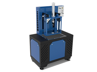
Torque Converter Welder
This torque converter welding machine is designed and adjusted in accordance with all the nuances, which may occur during the welding halves of a torque converter serving as a key in solving TC Problems. Various modes are offered to suit Customers' volumes and preferences: the unit can be used for usage of one or two welding guns.
FEATURES:
-
Rigid structure and use of high-precision mechanisms and parts
-
Recovery of key clearance allowance of run-out and axial play
-
Convenient control with a single touch panel
-
Detailed menu in different languages
-
Precise location of gas-burner mechanism and measuring tools
-
Possibility of easy impeller hub replacement
-
Additional buttons of manual control (add-on feature)
-
The welder comes as standard with one Welder for regular production. In addition it can be upgraded to a dual gun welding.
-
Industrial touch screen display allows a simple operation with or without protective gloves
-
Comprehensible and modern style control panel for swift and comfortable navigation
-
Ethernet and USB-sockets for ease of software updates
Undoubtedly The Most Advanced Torque Converter Welder Available In The Market

FEATURED PRODUCT:
WS 3.2 TORQUE CONVERTER WELDER

New Features of WS 3.2 Torque Converter Welder
-
Hardware of the torque converter welding stand runs by our HTC-S Controller - allowing for ease of software updates and firmware upgrades.
-
Increased rotation of the turntable (up to 60 rpm) - allowing for extra quick placement of the welding points. Movements between the 2 welding points (even 180 degrees opposite) is done in less than 1 second. This fully prevents metal deformation and guarantees precise alignment.
-
Touch screen control panel, duplicating the main operating modes with physical buttons. This allows the user to still use emergency mode for manual control even if the touch screen computer gets somehow damaged.
-
Removable stainless steel panels in the welding area - for additional protection from welding splatter.
-
Additional lighting of the work area with a separate switch on the control panel.
-
Exhaust fan to remove the by-products of welding.
-
Screen covering the work area to protect the operator during the work cycle.
-
Steel Set-tru precision chucks and high precision bearings - you achieve the highest standard of accuracy.
-
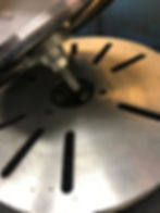
Special marks on the faceplate with a pointer allowing the most accurate positioning of the welding torches - with an additional button of return to the '0' position to initiate the welding process.
-
Simplified procedure of updating to the 2-gun welding stand - in case of especially high volumes - with easy software reload process.
Dual Chuck System

Due to the fact that the variety of repaired torque converters during the working day can be quite high, technicians have to deal with torque converters of various sizes. To increase the efficiency of labor, it is necessary to speed up the preparatory and finishing operations. That is why three-jaw self-centering chucks with a manual drive are used as locking elements to accelerate the torque converter installation on the welding stand. It allows technicians to install torque converters with various diameters of the hub and the pilot on the stand without any additional manipulations. Clamping force of chucks is sufficient to lock-up the torque converter during the welding process and to provide the required accuracy at the final stage of repair.
While using collet chucks, it will be necessary to change collets each time when diameters if the hub and pilot of the torque converter being repaired differ from dimensions of the preceding unit, resulting in time-consuming stand readjustments. In case of using adapter sleeves/bushings, there may be some doubts regarding reliability of the torque converter locking, and there is also a chance of a clearance between the bushing and the hub (pilot). The clearance size is a location/positioning error, which subsequently results in misalignment between the hub and the pilot. The misalignment will only increase during welding.
Electronic Control

Hydra-Torque WS 3.2 torque converter welder electronic control system allows technicians to adjust the speed of welding, switching from welding to rotating mode with very high accuracy. At the stage of welding it is extremely important to synchronize the torque converter rotation with the moments of welding starts/stops. It is also necessary to have a wide range adjustment for different parameters (rotation speed, number of welding dots, etc). This control system allows setting the welding speed by entering the torque converter diameter, which greatly simplifies the welding stand setup. Moreover, it is also possible to change the vertical positioning level of the spindle (upper chuck). In addition, this simple and user-friendly control system makes it easy to change the interface language and measuring units. All the mentioned factors put such a system well above any analog solutions.

ACCUTURN is a patented solution for Hydra-Torque 3rd generation torque converter welders. One of the major causes of misalignment is unequal cooling of torque converter welding spots. This technology allows to minimize misalignment of two halves of a welded torque converter. With the ACCUTURN feature, the time period between 2 welding spots that are located diametrically opposite (it means 180 degrees to each other) is less than a second. Rotation speed of the turntable between the weld spots is increased due to the use of a powerful stepper motor. The worm drive compensates high inertia loads when putting tacks at high revs, allowing for almost instant faceplate stopping.
Other Features


The torque converter welder boasts several notable features. Firstly, it incorporates the use of precision laser positioning to ensure accurate placement of welding guns, particularly when utilizing the dual gun welding option available in the WS welder model. Additionally, the HD (Heavy Duty) welder option showcases a spacious 450 mm faceplate, offering ample working area for welding tasks requiring extra strength and durability. Furthermore, the inclusion of the NOGA console enhances convenience by securely holding welding torches in place during operation.
Additional tools for Torque converter shop

The balancer is used for checking the outer shell of a Torque Converters on the subject of uneven weight distribution. Just imagine an unbalanced Converter inside an Automatic Transmission and the harm it may do when rotating at high RPM values and you will understand its use. Car services implement these tools to avoid any disagreements with their Customers and ensure high-class remanufacture, though many rebuilders tend to rely on their expertise and produce quality results without them.
Internal clearance check stand
Also known as end-play gauge stand, this tool gained popularity thanks to simplicity and efficiency. The dial gauge indicates how the internal elements of a Torque Converter are positioned within the housing. A large clearance will lead to throbbing, while a small one will result in redundant stiffness. In both instances, there will be a negative impact on the general transmission performance. This compact tool plays a key role in avoiding such situations.

Torque converter leak tester
The mechanism of compressed-air supply employed in the stand facilitates detection of leaks in a rebuilt converter unit. If a welding seam was done badly and there are leaks in a rebuilt converter unit, air pumped into the TC submerged into water will show air bubbles pinpointing the location, so even tiny gaps will be revealed. Such testing method is both effective and visually compelling.
After the air-test check the converter unit undergoing rebuilding is subsequently integrity-confirmed or is subject to additional welding, which is regularly easy to complete manually.

Welder and Bonder at customers transmission shop

Older model of welding stand. Out of production
FREQUENTLY ASKED QUESTIONS
What welders are provided with the machine? We supply JASIC TIG 250 welder in our torque converter welding machines.
Can I order it without welders and supply my own? Yes. Please specify you with to order the machine with the “Welder Delete” option. This allows you to source a comparable Lincoln or Miller welder to use in the machine.
What kind of a welding algorithm does the welder have to keep distortion to a minimum? The torque converter welder uses an 8 point welding algorithm as it rotates the torque converter. The first 7 points are evenly spaced tack welds with the last point initiating the full weld circle. This process is automatic once started and keeps distortion to a minimum.
Hydra-Torque equipment electrical technical requirements: The Torque Converter Welder for the US comes as 230V/50-60Hz/3-Phase standard. Other voltage configurations are available upon request and can be quoted and specified at the time of order.
Additional tools required for rebuilders of Torque Converters:
-
Lathe for cutting open the torque converter.
-
Quality parts cleaning system.
-
Torque Converters spare parts.
Where can I get pare parts for Torque Converters? Most popular parts for the Torque Converter would be friction linings, friction plates / discs, O-rings, seal rings. Local suppliers or international torque converter rebuild parts vendors can provide you with all spare parts for both valve body and torque converter repairs. Hydra-Test can advise or recommend viable options if needed.
Which gas mixture is required? Typically, 80% СО2 / 20% argon (other typical transmission workshop gas mixtures are also appropriate). The torque converter welder wire is the 0.8mm diameter.
TORQUE CONVERTER IMPELLER HUB REPLACEMENT TOOL


There are different methods used for hub replacements. The preferred method comes down to personal choice. Depending on your torque converter repair equipment and the lathes available, some customers will remove the damaged hub before separating the torque converter as this means your hub machining would be true to the spigot on the front cover, which is held in the lathe when separating the torque converter.
Other clients would separate the converter first and then hold the outside of the impeller in a lathe with opened jaws. Hence holding and machining only the lid instead of the entire converter. This method allows you to inspect the internals and either side of the lid before you start machining the hub.
Regardless of which method you use, you do need to measure the height of the original hub before you start the machining process. The next step is to decide whether you want to use the flanged or butt mount style replacement hub. Butt mounted hubs are easier to fit in terms of machining as all you need to do is to cut off the damaged hub and then machine a perfect stepped hole based on the outer diameter of the replacement hub. Therefore, a hole of the size of the replacement hub will centralize the hub and then simply machine the depth until your hub sits at the same height as the original.
The only negative with this method is that the replacement weld is right up against the edge of the hub and you need to make sure that it is not too high or too big because it could interfere with the pump seal on installation.
The flanged hub replacement is easier to weld in place as the replacement weld is further out from the hub but the machining can be more complicated on occasion when trying to achieve the same height as the original. This is dependent on type but generally easier to achieve if you have the option of holding the lid independently on a lathe with opened jaws.
Once the damaged hub has been removed and a replacement fits into a machined hole at the same height as the original, it needs to be welded in place. We suggest that MIG welding is used for this process unless you are a skilled and trained TIG-welder. In our experience TIG welding is too hot and quite badly discolors or distorts the hub.
Before welding, the hub needs to be held in place and the impeller needs to be centralized on the turntable of the welding machine. The hub itself does not need to be centralized on the impeller as the hole size should be exact and this means that the hub is automatically centralized as long as the impeller was held centrally when machined.
The recommended option of holding the hub in place is to machine adapters to fit perfectly inside the hub and is held in the top jaws of the welder. This process aligns the impeller hub for you and holds the hub in place for welding. Just make sure that the impeller is fixed to the turntable so that it will turn with the table when welding.